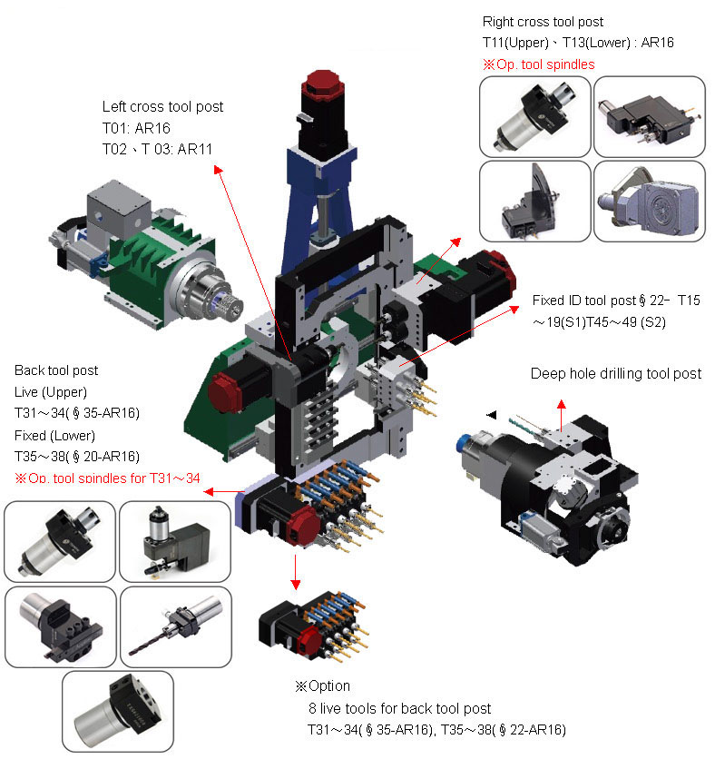
Swiss-Turn Gang tool type ML206


Tool capacity:
Number of tool positions
28
Number of mountable tools
Maximum 39, depending upon actual tool mounting layout and optional tooling parts
OD tool (T04 ~ 08, 21 ~ 23)
8 (T04 ~ 08, 21~ 23)
Face fixed ID tool
5 (T15 ~19)
Face deep-hole drilling tool
2 (T91,92)
Back fixed ID tool
4 ~ 9 (T35 ~ 38, 45~49)
Cross live tool
5 (T01 ~ 03, 11, 13 )
Face live tool
0 ~ 4(T11, 13) , depending upon that if cross tool spindles on T11,13 are interchanged with double- face end-working tool spindles or not
4 ~ 8 (T31 ~ 34,11,13). See“Face live tool”
Model
ML-206
machining capacity
Main spindle
Bar stock diameter
∮3 ~20 mm
Max. machining length
210 mm ( Motor direct - drive guide bushing)
250 mm ( Fixed type guide bushing)
80 mm ( Mechanical-drive guide bushing )
45 mm (Guide bushing-less )Drilling
∮10 mm
Tapping
M8
Deep hole drilling
∮8 mm
Back spindle
Max. work chucking diameter
∮20 mm
Drilling
∮8 mm
Tapping
M6
Live tool spindle
Drilling / tapping (Left cross tool)
∮6 mm / M5
Drilling / tapping (Right cross tool)
∮8 mm / M6
Drilling / tapping (Back tool)
∮6 mm / M5
Max. slitting saw / slotting cutter dia.
∮30 mm (T01)
Speed
Main spindle
200 ~12,000 min-1
Back spindle
200 ~12,000 min-1
Rotary guide bushing
200 ~12,000 min-1 ( Motor direct - drive) 200 ~8,000 min-1 ( Mechanical-drive )
Tool spindle
200 ~8,000 min-1
Controllable axes(including Cs axes)
8 axes
Rapid traverse (m/min)
32 (X1,Y1: 24) (Y2 : 15)
OD tool shank
12 × 12 × 100 mm
Tool positions / Max. mountable tools
28/39
Motors
Main spindle
2.2 / 3.7 KW( Cont. / 15 min )
Back spindle
1.5 / 2.2 KW( Cont. / 5 minutes)
Tool spindle
Left cross tool
0.75 KW
Right cross tool
1.0 KW
Back tool
0.5 KW
Rotary guide bushing
0.75 / 1.1 KW( Cont. / 15min)
X1.X2.Z1.Z2.Y2 axes
0.5 KW
Y1 axis
0.75 KW
Coolant pump
0.75 KW
Lubricating pump
0.011 KW
Axis travel
X1
124 mm
Y1
280 mm
Z1 ( Fixed guide bushing )
250 mm
X2
340 mm
Y2
60 mm
Z2
300 mm
Power, etc
Weight
3,200 Kg
Power source requirement
14.3 KVA
Compressed air requirement
≧ 4 Kg / cm2
Air consumption
40 NL / min
Width × depth × height
2,110 × 1,200 × 1,885 mm
Standard NC Specifications:
Controller
FANUC 32i-B
No. of controlled axes
8 (X1,Z1,Y1,C1,X2,Z2,Y2,C2)
Spindle synchronous control (speed&phase angle)
S1- S2 (Main spindle -Back spindle )
Axis synchronous control
Z1-Z2, C1-C2
Axes simultaneously controlled
Max. 4 axes / each path
Axis composite control
X1-X2 , Z1-Z2
Max. programmable dimension
± 8 digits
Rapid traverse rate
32 m / min (X1, Y1, Y2: 24 m / min)
Spindle / Feed rate override
0 ~150%, 10% increments
Tool offset pairs
±6 digits 200 pairs
Display unit
10.4”color LCD
Part program storage length
512 Kbyte (equivalent to 640 m tape for each path system)
Programs stored
1,000
Standard accessories:Main spindle sleeve (for round bar machining)
Back spindle sleeve (for round bar machining)
Door interlock(Tooling zone side door / Main spindle side door )
Coolant pressure switch
Spindle cooling unit
Standard tools
Transit clamps
Automatic power shut-off
Back spindle air purge
Cross live drill air purge
Coolant pump(0.6∼1.0MPa)
Internal work light
Manual pulse generator
3-tiered warning lamp set
Cut -off sensor
Work catcher
Work conveyor


